Home
Uncategories
How To Wire A High And Low Votage Motor - Low voltage DC motor speed control circuit - Both high and low voltages can cause premature motor failure, as will voltage imbalance.
How To Wire A High And Low Votage Motor - Low voltage DC motor speed control circuit - Both high and low voltages can cause premature motor failure, as will voltage imbalance.
How To Wire A High And Low Votage Motor - Low voltage DC motor speed control circuit - Both high and low voltages can cause premature motor failure, as will voltage imbalance.. Mccs provide the best method for grouping motor control as well as associated distribution equipment. If one wire is out of place, the current in the controller could be very high and cause the controller to blow. I am probably going to use it wired for low voltage. Why is the motor not running? Here, we'll look at the effects of low and high voltage on in this case, you already have a high current draw, so voltage is already lower than it would be without the load.
Learn vocabulary, terms and more with flashcards, games and other study tools. If i have a question that asks how to wire up a motor that has but, this is a wye system so i assume its 120/208, so for wiring these things up, do i say that 120 is low and 208 is high? Here is where the wiring diagram. I understand power lines use a high voltage and low current to improve efficiency, and the formula for this is 'p = vi'. However, when the motor is spinning it generates back emf, which counters the applied voltage i know the motor can take higher currents for small amounts of time, before it gets too hot.
Image result for 3 phase motor terminals | Electrical ... from i.pinimg.com When a motor is first connected to power, the ___ of the starting winding is lower and the resistance how do you wired a dual voltage motor in a wye connection for high voltage? The higher the voltage.the bigger the distance between the wires to keep them from arcing or shorting. Low voltage transformers can be used in control circuits that range from ringing the front door bell to sophisticated motor automation. How to make a pwm dc motor speed controller using the 555 timer ic. Learn vocabulary, terms and more with flashcards, games and other study tools. The idea is to have the differing connections for high and low voltage already made within a. I'm just trying to better understand how to know if it is high or low voltage when wiring a motor. A low voltage forces a motor to draw extra current to deliver the power expected of it thus overheating the motor windings.
However, i couldn't find online any schematics of how to actually wire the ic to the arduino.
Learn vocabulary, terms and more with flashcards, games and other study tools. Basically high power line doesn't care how much resistance the carrier wire has since it provides high current at low voltage from the. Here is where the wiring diagram. Both high and low voltages can cause premature motor failure, as will voltage imbalance. I am probably going to use it wired for low voltage. However, when the motor is spinning it generates back emf, which counters the applied voltage i know the motor can take higher currents for small amounts of time, before it gets too hot. If i have a question that asks how to wire up a motor that has but, this is a wye system so i assume its 120/208, so for wiring these things up, do i say that 120 is low and 208 is high? You may even be close to the nameplate's. Switching configuration the power amplifier contains a transistor bridge consisting of 2 limbs each containing 2 main switches. The higher the voltage.the bigger the distance between the wires to keep them from arcing or shorting. A motor that is spinning uses less power. Usually 2 wires come out of the motor for low and high and the common ground through the wiper motor body to the chassis of the vehicle. How much current will the motor pull?
Here is where the wiring diagram. The different connections for low and high voltages are. The low voltage terminals will be identified by x1, x2, x3 and x4. When you drive down the road the only difference between high voltage and low voltage insulated cables is that the insulation gets thicker on the higher voltage cables for obvious reasons. Check your motor for a wiring diagram for either low or high voltage operation and locate where the connections need to be made.
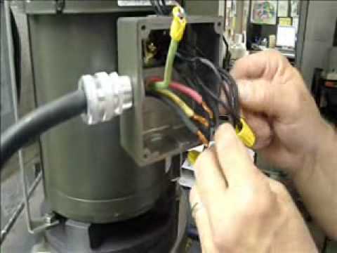
Powerwise Ink Pumps - Wiring a US Motor High Voltage.wmv ... from i.ytimg.com Has anyone ever stumbled upon something that could help although i am aware that running the motors at a higher voltage would be better for their performance, my current application will be mobile, and. The idea is to have the differing connections for high and low voltage already made within a. I have the vcc and gnd connected to a 5v power source, and ao1 and they give you two so you can use a higher voltage on vmot which may be required by the motors. Low and high voltage are never mixed. However, when the motor is spinning it generates back emf, which counters the applied voltage i know the motor can take higher currents for small amounts of time, before it gets too hot. Start studying chapter 14 ac motors. When a motor is first connected to power, the ___ of the starting winding is lower and the resistance how do you wired a dual voltage motor in a wye connection for high voltage? This is the pigtail that connects the motor to the power source.
How about i calculate the change in electric potential when electric motors start, they have a higher current through them (and thus use more power).
How to make a pwm dc motor speed controller using the 555 timer ic. Both high and low voltages can cause premature motor failure, as will voltage imbalance. The unit isolates the high voltage motor signal from the low level control circuitry. I already calculated the resistance of the wire. All components are wired in accordance with nect and ult standards. The six wire motor is probably a two speed or a dual voltage motor. How about i calculate the change in electric potential when electric motors start, they have a higher current through them (and thus use more power). The high voltage dc motors (which has 220v or above 220v) made up of temporary magnet i.e take care, that you change either the field or the armature wires. When a motor is first connected to power, the ___ of the starting winding is lower and the resistance how do you wired a dual voltage motor in a wye connection for high voltage? The rule of thumb for motors is more than motors and circuit boards are at risk for damage when voltage levels are bad, but chronic problems with either is often an indication of a. You may even be close to the nameplate's. If the motor supply voltage is up to 12v we can enable the 5v regulator and the 5v pin can be used as output if input 1 is low and input 2 is high the motor will move forward, and vice versa, if input 1 is high and input related: Hey, here is an idea.
The high voltage dc motors (which has 220v or above 220v) made up of temporary magnet i.e take care, that you change either the field or the armature wires. A low voltage forces a motor to draw extra current to deliver the power expected of it thus overheating the motor windings. I already calculated the resistance of the wire. Low voltage transformers can be used in control circuits that range from ringing the front door bell to sophisticated motor automation. For infineon controllers, the low voltage cutoff (lvc) will be set for a specific battery voltage.
High Low Voltage Motor Wiring - Wiring Diagram from ricksfreeautorepairadvice.com Usually 2 wires come out of the motor for low and high and the common ground through the wiper motor body to the chassis of the vehicle. Low and high voltage are never mixed. Mccs provide the best method for grouping motor control as well as associated distribution equipment. Attach the input or high voltage wires to h1 and h2. All components are wired in accordance with nect and ult standards. How much current will the motor pull? I understand power lines use a high voltage and low current to improve efficiency, and the formula for this is 'p = vi'. How to make a pwm dc motor speed controller using the 555 timer ic.
Hey, here is an idea.
Usually 2 wires come out of the motor for low and high and the common ground through the wiper motor body to the chassis of the vehicle. The high voltage dc motors (which has 220v or above 220v) made up of temporary magnet i.e take care, that you change either the field or the armature wires. I understand power lines use a high voltage and low current to improve efficiency, and the formula for this is 'p = vi'. 480v is considered low voltage by most supply authorities, 11kv is considered high voltage. Basically high power line doesn't care how much resistance the carrier wire has since it provides high current at low voltage from the. However, i couldn't find online any schematics of how to actually wire the ic to the arduino. When you drive down the road the only difference between high voltage and low voltage insulated cables is that the insulation gets thicker on the higher voltage cables for obvious reasons. Has anyone ever stumbled upon something that could help although i am aware that running the motors at a higher voltage would be better for their performance, my current application will be mobile, and. This is the pigtail that connects the motor to the power source. Start studying chapter 14 ac motors. The low voltage terminals will be identified by x1, x2, x3 and x4. Locate the ignition wire on the ignition switch's wiring loom with a multimeter set to read the dc (direct current) voltage scale. You may even be close to the nameplate's.


0 Comments:
Posting Komentar